Digital Logic Circuits and Components
- Digital Computers
- Logic Gates, Boolean Algebra
- Map Simplifications
- Combinational Circuits
- Flip-Flops
- Sequential Circuits
- Integrated Circuits
- Decoders
- Multiplexers
- Registers and Counters
- Memory Unit.
Digital Computers
A digital computer is an electronic machine that processes information using binary (0s and 1s). It consists of:
- Central Processing Unit (CPU): Controls operations and executes instructions.
- Memory (RAM, ROM): Stores data and programs.
- Input/Output (I/O) Devices: Communicates with external devices.
- Bus System: Transfers data between components.
A digital computer works on binary arithmetic and logic operations, making digital logic circuits fundamental to its operation.
Logic Gates
Logic gates are the basic building blocks of digital circuits. They process binary signals (0 and 1) based on Boolean algebra.
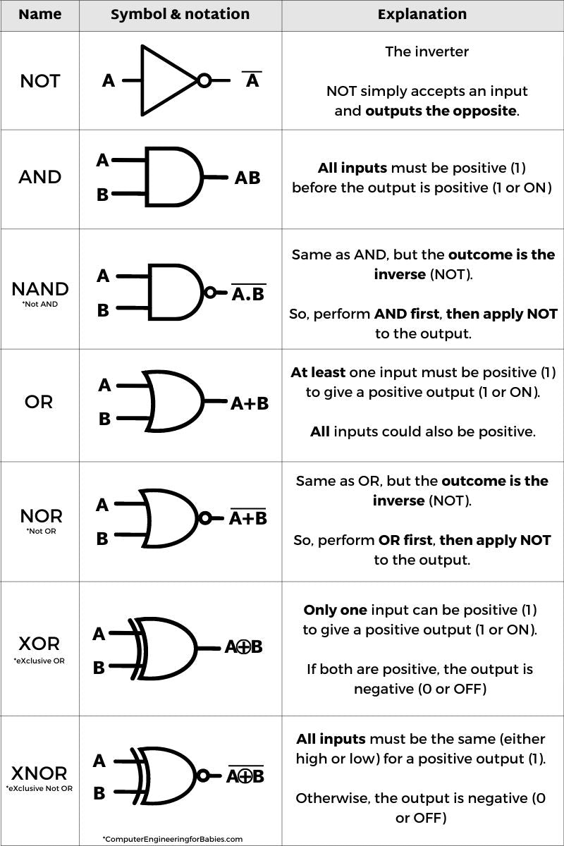
Basic Gates:
| Gate | Symbol | Operation |
|---|---|---|
| AND | ∧ | Output is 1 if both inputs are 1 |
| OR | ∨ | Output is 1 if at least one input is 1 |
| NOT | ¬ | Inverts the input (0 → 1, 1 → 0) |
Universal Gates:
- NAND (NOT AND): Output is 0 only if both inputs are 1.
- NOR (NOT OR): Output is 1 only if both inputs are 0.
- XOR (Exclusive OR): Output is 1 if inputs are different.
- XNOR (Exclusive NOR): Output is 1 if inputs are the same.
NAND and NOR gates are universal because all logic circuits can be built using only them.
3. Boolean Algebra
Boolean algebra simplifies digital circuits using logical operations:
- Idempotent Law: A + A = A, A · A = A
- Complement Law: A + A’ = 1, A · A’ = 0
- De Morgan’s Theorem:
- (A · B)’ = A’ + B’
- (A + B)’ = A’ · B’
Boolean algebra helps in simplifying logic circuits by reducing the number of gates.
Absolutely! Let’s stick with the “light switch” + kid-friendly style to explain these three important concepts in Boolean Algebra.
Idempotent Law:
“Doing it twice is the same as doing it once.”
1. A + A = A
Imagine you have a switch A.
If you say “If A is ON OR A is ON”, that’s still just A is ON.
🧠 You’re not making it any more ON by repeating it.
| A | A + A |
|---|---|
| 0 | 0 |
| 1 | 1 |
2. A · A = A
This is like saying “A AND A” — which is still just A.
🧠 If the same switch is needed twice to turn on the light, it’s no different from needing it once.
| A | A · A |
|---|---|
| 0 | 0 |
| 1 | 1 |
Complement Law:
“A and its opposite always cancel out.”
1. A + A' = 1
This is like saying:
💡 “If switch A is ON OR switch A is OFF, will the light turn ON?”
Yes! One of them has to be true.
| A | A’ | A + A’ |
|---|---|---|
| 0 | 1 | 1 |
| 1 | 0 | 1 |
2. A · A' = 0
💡 “If switch A is ON AND A is OFF at the same time?”
That can never happen — it’s a contradiction. So the light is OFF.
| A | A’ | A · A’ |
|---|---|---|
| 0 | 1 | 0 |
| 1 | 0 | 0 |
De Morgan’s Theorem:
“Flip the group, change AND to OR (or OR to AND).”
This is a magic trick to simplify logic when there’s a NOT outside a group.
1. (A · B)' = A' + B'
Say:
“If both A AND B need to be ON for light, and I say NO to that, what’s actually happening?”
👉 You’re saying: “Either A is OFF OR B is OFF”
| A | B | A·B | (A·B)‘ | A’ | B’ | A’+B’ |
|---|---|---|---|---|---|---|
| 0 | 0 | 0 | 1 | 1 | 1 | 1 |
| 0 | 1 | 0 | 1 | 1 | 0 | 1 |
| 1 | 0 | 0 | 1 | 0 | 1 | 1 |
| 1 | 1 | 1 | 0 | 0 | 0 | 0 |
✅ Left and right sides match!
2. (A + B)' = A' · B'
“If A OR B turns the light ON, and I say NO to that, it means BOTH A and B must be OFF.”
| A | B | A+B | (A+B)‘ | A’ | B’ | A’·B’ |
|---|---|---|---|---|---|---|
| 0 | 0 | 0 | 1 | 1 | 1 | 1 |
| 0 | 1 | 1 | 0 | 1 | 0 | 0 |
| 1 | 0 | 1 | 0 | 0 | 1 | 0 |
| 1 | 1 | 1 | 0 | 0 | 0 | 0 |
✅ Both sides match again!
4. Map Simplifications (Karnaugh Map - K-Map)
A K-map is a visual method of simplifying Boolean expressions by grouping adjacent 1s in a truth table.
- Uses 2, 3, 4, or more variables.
- Groups 1s in powers of 2 (1, 2, 4, 8).
- Reduces complex logic functions into minimal SOP (Sum of Products) or POS (Product of Sums) form.
Example:
AB | 00 | 01 | 11 | 10 | --- |----|----|----|----| 0 | 0 | 1 | 1 | 0 | 1 | 1 | 1 | 0 | 0 |Groups: (A’B) + (AB’)
Result: A ⊕ B (XOR Gate)
5. Combinational Circuits
Combinational circuits do not store past inputs (no memory). Their output depends only on the current inputs.
Examples:
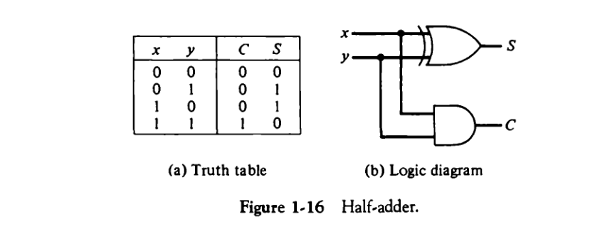
- Half Adder – Adds two binary digits (A, B)
- Sum (S) = A ⊕ B
- Carry (C) = A · B
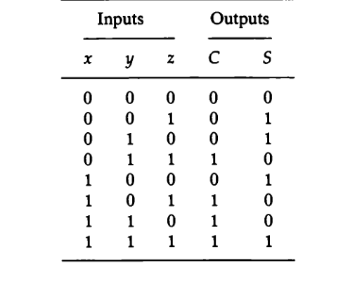
- Full Adder – Adds three binary digits (A, B, Carry-in)
- Sum (S) = A ⊕ B ⊕ Cin
- Carry (Cout) = A · B + Cin (A ⊕ B)
-
Subtractor: Performs binary subtraction using XOR, AND, and NOT gates.
-
Multiplexer (MUX): Selects one input from multiple inputs based on a selector.
- 2:1 MUX: Y = S’ A + S B
-
Demultiplexer (DEMUX): Sends one input to multiple outputs.
6. Flip-Flops (Sequential Circuits)
Flip-flops are memory elements that store one bit. They are the building blocks of registers and counters.
Types of Flip-Flops:
| Type | Symbol | Function |
|---|---|---|
| SR Flip-Flop | S-R | Stores data based on Set (S) and Reset (R) inputs |
| D Flip-Flop | D | Stores input D at clock pulse |
| JK Flip-Flop | J-K | Eliminates indeterminate state of SR flip-flop |
| T Flip-Flop | T | Toggles between 0 and 1 |
Example: D Flip-Flop Truth Table
| D | Q(next) |
|---|---|
| 0 | 0 |
| 1 | 1 |
Clocked Flip-Flops are used in counters, registers, and memory units.
7. Integrated Circuits (ICs)
Integrated Circuits combine multiple logic gates on a chip.
IC Classifications:
- SSI (Small Scale Integration) – Few gates (AND, OR, XOR)
- MSI (Medium Scale Integration) – Adders, Decoders, Multiplexers
- LSI (Large Scale Integration) – Processors, Memory Chips
- VLSI (Very Large Scale Integration) – Microprocessors, FPGAs
VLSI circuits power modern CPUs, GPUs, and embedded systems.
8. Decoders
A decoder converts binary inputs into a single active output.
Example: 2-to-4 Decoder
| A | B | Output |
|---|---|---|
| 0 | 0 | 0001 |
| 0 | 1 | 0010 |
| 1 | 0 | 0100 |
| 1 | 1 | 1000 |
- Used in memory address decoding.
9. Multiplexers
A multiplexer (MUX) selects one input from many based on control lines.
Example: 4-to-1 MUX
Y = A S0’ S1’ + B S0 S1’ + C S0’ S1 + D S0 S1
- Used in data routing and CPU registers.
10. Registers and Counters
A register is a group of flip-flops used for temporary storage of data in CPUs.
- Shift Registers: Shift data left or right (used in serial communication).
- Parallel Registers: Store multiple bits at once.
A counter is a register that increments or decrements values based on clock pulses.
Types of Counters:
- Asynchronous Counter – Ripple effect (slower)
- Synchronous Counter – All flip-flops triggered at the same time (faster)
- Up/Down Counter – Counts up or down based on control input
- Ring Counter – Circular shift of bits
11. Memory Unit
A memory unit stores and retrieves data in a digital system.
Types of Memory:
- Primary Memory (RAM, ROM) – Fast, volatile (RAM), non-volatile (ROM)
- Cache Memory – Small, fast memory between CPU and RAM
- Secondary Memory (HDD, SSD) – Stores permanent data
- Registers – High-speed temporary storage in CPU
Memory is organized as word addressable or byte addressable.